 R i d o l f a . eu
Magnetic Levitation and Wireless Power Transfer
Published August 2019 in None
I was fascinated by pictures showing items hovering in the air. So, why not start my own magnetic levitation project? First I considered using a controller such as an ESP8266 but then a KY-024 board in my spare parts box changed my mind and the outcome was a hardware-only project without any additional code. Thinking about a good presentation for the hovering item, I finally came up with another idea: an integrated wireless power transfer. The nice wooden parts have been turned by a friend.
 |
 |
 |
 |
 |
 |
Project Details
In my case magnetic levitation means to have a magnetic item that will be attracted by an adjustable magnetic field. The basic rule of levitation is simple: if the gravitation is too high and the item is about to fall down, increase the magnetic attraction and vice versa. Magnetic item simply means: take a lightwight (~ 30gr) item and glue a small permanent magnet on top of it. If the item is made of magnetic material, so much the better, then no glue is needed. In principle it's also not rocket science to generate an adjustable magnetic force: take a solenoid, watch the item's movement and switch the solenoid on and off, so that the item will hover in the air. Wireless power transfer can e.g. be achieved by a "transmitter coil" that produces a alternating magnetic field which induces a current flux in a receiver coil. Two coils and a little bit electronics, that's it. Both cases sound too good to be true and in fact, as decribed below, I had to overcome some obstacles from theory to a working example. There isn't just one way of doing it but at this point I'll only describe my project.
Bill of Material
I assume that you have a well-equipped spare box. The list shows some examples of items that you need. The schematics show additional items.
- 1 KY024 board
- 5m enamelled copper wire, CU 0,22 [to wind the magnetic coil]
- 1 TIPP 122 (or similar) transistor [electromagnet driver]
- 3 resistors ( 100k, 50k,20k )
- 2 capacitors (2uF, 1nF)
- 1 diode 1N3008 or similar [flyback diode]
- 2 permanent magnets 5mm*3mm N45 [I assume that similar magnets will work as well, just try it]
Schematics and Electronic Board
The schematics are created with KiCad and can be downloaded as PDF files.
- Schematics Download
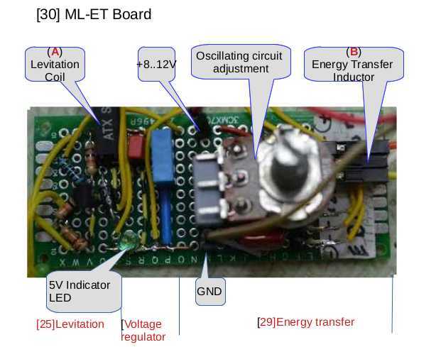
- Schematic1 Levitation and coil driver
- Schematic2 Energy transmitter/oscillator
- Schematic3 Power regulator
 Electronics 1 Electronics 1 |
 Electronics 2 Electronics 2 |
Magnetic Levitation
To hover the item, a defined magnetic field is needed, produced by an electromagnet and multiple permanent magnets. A hall sensor measures the induced field. The output signal is a voltage corresponding to the field strength. Depending on the Q-point deviation the electromagnet switches on and off with a frequency of appr. 9kHz. The KY024 board has a hall sensor(type 49E) and does the job. Later on I realized that a modification of the board was necessary for it to work properly. As the KY024 is not able to switch the electromagnet's current of about 300mA, therefore an additional driver transistor is needed.
The Electromagnet
It may be that you have an appropriate electromagnet which you can use. Try it. Unfortunately I didn't and a new project was born: a simple coil winding machine (coil-winding). But this is a different story. My electromagnet has the following key figures:
- 1500 windings
- CU 0,22
- 26 Ohm
- D = 15mm
- d = 7mm
- l = 22mm
- M6 screw
 Electromagnet Electromagnet |
 Hall sensor Hall sensor |
 Electromagnet on/off frequency Electromagnet on/off frequency |
Modifying the KY024 Board
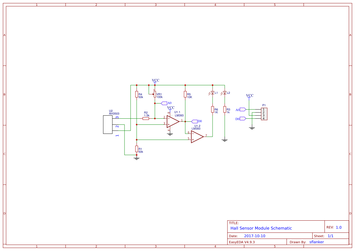
First unsolder or cut off the hall sensor. Extend the 3 pins with flexible wires and then solder the sensor (wires) back to the board again. The wire length depends on your final layout but 15cm should suffice. Now to the more difficult part. Unfortunately the reference voltage of the comparator LM393 (Pin3+) is fixed to half (2.5V) of the supply voltage of 5V. ( R1, R2). This means that we can not use the full voltage range of the hall sensor output to determine the proper operating point. To adjust the reference voltage between 0V and 5V we have to modify the board. Easily said but not done.
- Schematics Download
- Schematic11 KY024 original schematic
- Schematic12 KY024 modified schematic
You have to unsolder the pot and cut through two conducting paths. Be aware that the board has conducting paths on both sides. Afterwards, solder the pot, two new wires and an additional resistor to the board. Perhaps you want to consider building a new device from scratch e.g. on a bread-board according to the schematic. The following images and hints might help to modify the KY024 board appropriately
 KY024 original board KY024 original board |
 KY024 modified board KY024 modified board |
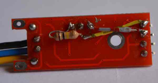 KY024 modified board KY024 modified board |
The Coil Driver
As mentioned the KY024 output is not able to switch the coil's current. That's why we need a driver. The file schematic-new.pdf shows a simple transistor switch. Keep in mind that this simple implementation inverts the KY024 output.
Wireless Power Transfer
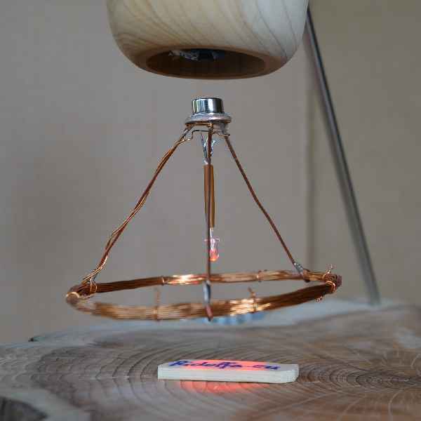
A condensator and an inductance create an oscillating circuit and produce an altering magnetic field (Transmitter). This field then generates a current in a second inductance (receiver) and thereby can power e.g an LED. That's exactly what we need. Hartley-Oscillator is the key word to understand the wireless power transfer. My transmitter coil has 110 windings in total with a central tapping at 55 windings and a diameter of appr. 80mm. I wrapped the coil around a bottle. The receiver coil has 30 windings, no central tapping, 50mm diameter.
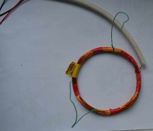 Transmitter Inductance Transmitter Inductance |
 Wood body with inductance Wood body with inductance |
Sensor and Magnet-Field Orientation
To find out the correct sensor and magnet field orientation, it's worth building a test arrangement.
| Transmitter Inductance |
 Wood body with inductance Wood body with inductance |
Permanent magnets and the solenoid must all have the same magnetic orientation. BTo ensure this,build a magnet stack where each magnet attracts the other and mark both sides with e.g. blue and red, shown in the following picture.
 Magnet Flux Magnet Flux |
If necessary change the electromagnet polarisation by changing the connecting wires.
The hall sensor should be mounted about 3..5mm below the electro magnet (screw). Therefore, some paper stripes are usefull.The more sensitive side of the sensor must point to the hoovering item, not to the screw. Don't forget the "support" magnet.